 |
(Update 24.
May 2018)
Starhawk Upright (Vectorbeam
1978) - Restore at 85%
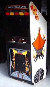 Current status as of 13. October 2007 Current status as of 13. October 2007
15. May
2005 -
Starhawk arrived from the U.S.
The game arrived safely as an import from www.coinopwarehouse.com
in the U.S. It is a very early b/w Vector Game from the Company
Vectorbeam which separated from Cinematronics. The picture is
"borrowed" from the Internet. My machine is in a not so good condition,
especially the bottom corners and the sideart is damaged.
Many thanks go to Paul from Pauls 50's here in Germany who helped me
with the customs and
shipping.
A first inspection showed that the game is technically wise complete,
which is very important. The cab is pretty solid and the monitor and
all other
electronics is very clean, nothing burned or "repairs" done. Mine is
missing the top artwork on the sides, but it seems it has never been
there.
9. October 2005
- Repair
of the electronics
Yesterday I removed all the electronics
incl.
monitor and the Control Panel from the machine and began to inspect the
electronics. Vectorbeam/Cinematronics games from this age are so called
Vector Games. The electron beam on the picture tube is deflected by two
coils in x (horizontal) and y (vertical) direction. That's why you will
often see the term XY game. The PCB's do not run on a normal Raster
Scan Monitor.
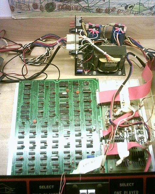
On the picture to the left you can see the large green CPU
board
which is made by far more than a 100 TTL chips, two 2k Roms and some
TTL PROMS. There is no "CPU" Chip on there, instead some of the TTL
chips form an ALU (Arithmetic Logic Unit) which performs all the
calculations and input/output. The whole game program is only 4K in
size. The RAM ist 12 bits wide and made by 3 * 9101 static RAM chips.
The CPU board can be used on other games like Speed Freak or
Space War(s) by using other game PROMs and another sound board.
Checking the CPU board did not reveal too much of interest. All of the
chips wer in place, no signs of previous repairs. One socket was empty,
which I found is ok, by comparing with an image on the Internet. Other
than removing the dust with a soft brush I did nothing.
The smaller PCB on the right is the Sound
Board.
Again, like the CPU board, no large scale integrated chips (like
synthesizers). The handful of sounds are created by discrete Logic and
their generation is triggered by the CPU via the output registers. On
the sound board located is also a driving circuit for the speaker. The
ispection of this board showed two 'exploded' 2.2uF/35V Tantalum
Caps. Those were filtering the +/- 25V from the Powersupply.
I
replaced them by two 'normal' electrolytic caps with a low ESR.
In the background you can see the (linear) Power
Supply.
It generates the +5V for the CPU board, +/-25V unregulated for the
sound board and the monitor and it also has some fuses to protect. Here
I did a good checking. WIth a defective powersupply you can really
harm the PCB's and the Monitor. I measured all of the diodes,
the
bridge
rectifier and the transistor (2N3055). After that I checked the fuses
and rewired the transformer for 230V (Europe!!!). Retightening the
screws on the large electrolytic caps is always a good idea. After
that I powered up the P.S. (w/o attaching the wiring harness and
measured all the voltages according to the schematics - everything fine.
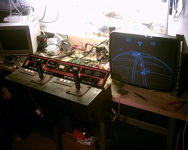
Now it's time to check the Monitor.
It is very
well built (Vectorbeam) and the PCB is of a good quality. I
also gave it a good clean and inspected it. Again, no repair was done,
nothing burned and nothing obviously broken. The monitor takes two
12bit inputs from the CPU board, applies each of the 12 bit words to an
DAC80 (D/A Converter) and after some amplification drives the two
deflection coils on the tube's neck. Also the board generates the High
Voltages for the picture tube. Scrolling thru some articles on the
Internet I decided to apply two modifications that were strongly
suggested the keep the delicate chips on the monitor board "alive".
Next item to look at was the Control
Panel.
Hey! The joysticks can never be broken. They are made of steel and I
would say 'indestructible". No microswitches but good old leaf
switches. No obvious problem visible - very good.
Now, it's time to
test the stuff !!!!!
- First step
-
attach the power supply to the CPU Board. No fuse blows....and check
the +5Volts.... everything
fine
- Second
step
- attach the Sound Board (w/speaker) to the CPU board and to power and
measure +/-15 Volts.... everything
ok, the two new caps on the sound board are staying quiet.
- Third
step
- Attach the monitor to the CPU board and to power. After powering up
the xy 'experienced" immediately recognizes the "chatter" of the
deflection coils. I really couldn't believe that this baby is working.
But then, no picture....hmm just a little fiddling with the brightness
and the picture was there. Good stuff, really :-) . ... everything ok
- Last step
is attaching the Control Panel. Well this revealed that some movements
could not be made. All three input latches 74LS151 had some bad inputs,
they were stuck low. Well the first repair, put in there good sockets
and the 74LS151's and ...
- wow, I
can coin it
up and play: a 27 year old game is back to life.
31. August 2007
- Cabinet
rebuild
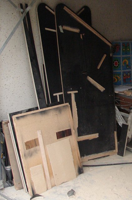
Two days ago I started to rebuild the
cab, as
the electronics needed a new 'home'. This was necessary because the
bottom of the cab had some damage and on the sideart
which I did not like and after my good results from rebuilding a
Tempest I decided to give it a go. BTW, I still do not have any idea
who will reproduce the sideart and kickplate art for me.
Material for the cab is 3/4" (19mm) particle board, coated with black
Melamin. I used black because no painting is required for the inner
parts of the cab. Using the original side panels as a reference the
measures were transferred to the new sides and then cut with a
router. Luckily the bottom and the rear were
at a 90° angle. For the rounded corner at the top and the front
bottom I made two templates.
The next step was the grooving of slots where the kickplate, the top,
the bottom and some other boards shall go to. It was quite difficult to
transfer the angles onto the new pieces. On the picture to the left you
can
see the two sides of the cab already finished with one
original
side in the front.
Now it was time to cut the various other boards with holes for venting
or the speaker. Sadly some boards' edges needed an angle as well, very
time consuming....
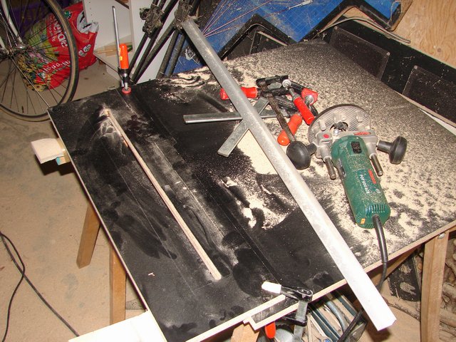
It was a
pretty dusty
work that I carried out in our garage. There's
maybe one or two days more to work until all wooden parts are rebuild
and until I can move with the work into my basement.
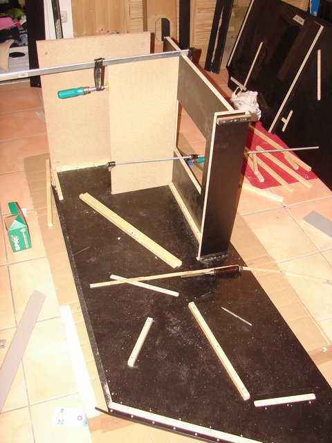
22. September 2007 -
Cabinet rebuild continues
Work has made good progress. To the
right you
can see the construction / assembling of the cabinet in my basement.
The principle of connecting the various pieces together is very similar
to the
original. Just that I use screws ( a lot of screws :) ), instead of
glue and nails. The most difficult part is the attachment of pieces at
a non-rightangle.
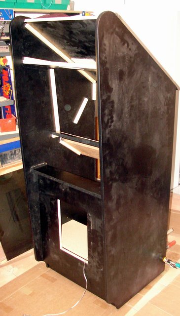
To the left, the cab is built together. A little dusty, I admit, but
the construction is very solid. The outer sides will get a white
sticker
with the artwork (work-in-progress).
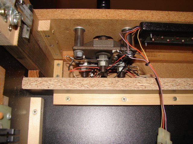
The attachment of the controlpanel (pic on the right) is different than
the original version. That used screws through the cabinet sides, ouch!
I
really wanted to avoid drilling holes thru my new cabinet sides, so I
decided to use clamps as they are known from pinballs securing the
head. BTW, have a look at the massive joysticks. It is really hard work
to play the games with this iron thingie.
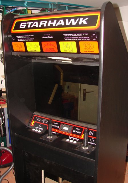
Now I fitted the marquee , the lighting behind it and the plexi in
front of
the monitor. Well, it starts to look more completely.
Here, to the right, the monitor, power supply and PCBs have been
fitted. The
coin mechs are lying around, because the coin door is not yet painted.
Now it was time to test that stuff. I checked all wiring twice and
flipped the power switch ......
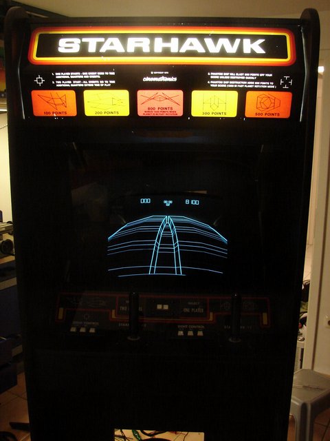
... and it works. For all of you, who have followed the story
until here,
there is a small video (9Mbyte) with the Starhawk gameplay and sounds :
starhawk.mpg
5. October 2007
- Sideart
reproduction starts
Now it's time to redo the artwork. For
the
Starhawk we have three different pieces. Two different pieces for the
Sideart and then also the Kickplate has some beautiful art. Starting
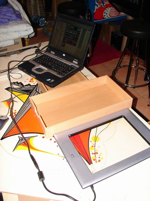
with the sides I scanned the graphics with an HP 4600 Scanjet. This
scanner is ideally suited because it has a rectangular shape and you
can see through the glass, how it is positioned on the original. In
total it required 11 scans for the large piece and 4 scans for the
smaller one. All in all ~450Mbyte of raw data. To the right you cab see
the actual scanning process. BTW it is worth noting to use some kind of
ruler/guide so that you can move the scanner allways in parallel
motion. The it is lateron easier to combine the individual scans..

To the left, eleven scans have been stitched together into one large
file, it was no that difficult. As software I used I-PhotoPlus which I
got together with one of my first scanners. Kind of cheap and I am sure
ther are many others like GIMP.
Now it
is time for
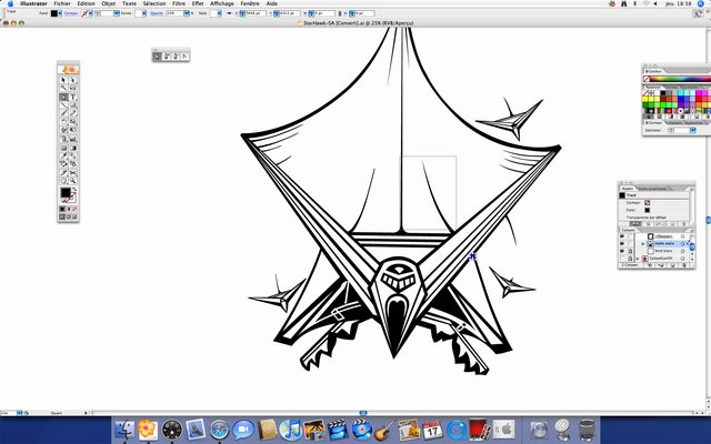
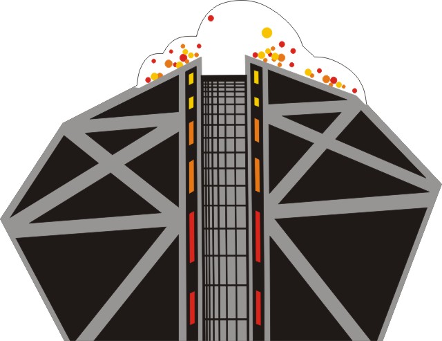
vectorizing the pictures. Luckily I got an offer for assistance by
Mathieu G. from France. So he is tackling the larger piece and making
good progress....
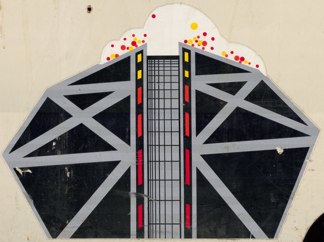
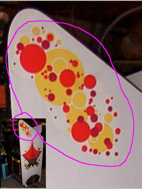
Now I am trying the smaller pieces of the sideart myself and the
results are not that bad. Software used is CorelDraw! Colors do not
match yet, but I have to check for that with Mathieu...
6.
October 2007 - Bad
news: One Sideart piece is missing
Oh dear, this piece is missing :-(
If you have good quality pictures of this piece of art, let me know.
Click here to Privacy Policy me.
13. October 2007 - Recording
sounds for MAME
While work on the sideart continues, I
was
made aware that in MAME the sounds of Starhawk are missing. So this is
not a problem, I will record it. The sound file required are noted in
MAME are those listed, but they are empty. As an appetizer you can hear
the explode and laser fire (open in a new window):
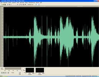
As a first try to find out how it works in MAME, I extracted the
complete soundtrack from my existing video with NERO WAVE EDITOR
(picture on the right). The sounds are unfortunately mixed somehow, so
even by cutting/blending the appropriate sections, they did not came
out perfectly. Then I saved them as .wav files in mono and 44100 sample
rate, added all together in a zip file "starhawk.zip", throwed them in
the 'Samples' Directory of MAME and voilá, it works. Small
glitch is that both, explosion and lasers, only start the sound when
they already supposed to end :-) , I think this is a small issue in the
MAME source. Now knowing that it basically works, I will get a good
recording and then supply it to the MAME folks.
» Starhawk - Links
Starhawk
Manual (2.6MByte) - I wish other manufacturers had such good
manuals
starhawk.mpg
- Starhawk game video incl. sounds
Cinematronics
Monitor FAQ 0.96 - Good introduction for Monitor &
Game Repair
History
of Cinematronics - title says it all
Cinematronics
Repair hints
Cinematronics
Monitor Repair hints - from crazykong
Cinematronics
HV Tech - Repairing the HV Unit
Tim
Skelly's History of Cinematronics and Vectorbeam
Cinematronics
on
ionpool.net - ROMS and various other good stuff.
|
 |