.: About Me
& Other Stuff
|
|
| .: |
Projects - Slam (MIRCO GAMES)
Restore :.
|
|
 |
(Update 24.
May 2018)
SLAM II Table (MIRCO
GAMES) - Restore
at 95%
Current status as of
14. March 2011
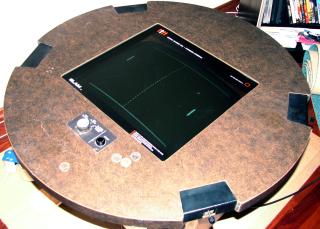
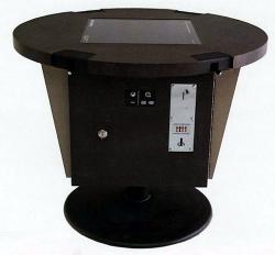 This is built in 1975 (tbc) by MIRCO GAMES in Phoenix/Arizona. Actually
there
is little information from the Internet, just two people looking for
schematics, which I don't have either. The units were built in 1975 per
the Arcade
Flyers Archive
(picture on right side) but I have a version II, which may be built
later. Its a Pong like b/w game for up to four players and
paddles
can be
moved across the screen in vertical and horizontal direction. There are
three play modes : AM(ateur), PR(ofessional) and against the
'Computer'.
In AM(ateur) mode the paddles are twice as large as in PR(ofessional)
mode.
This is built in 1975 (tbc) by MIRCO GAMES in Phoenix/Arizona. Actually
there
is little information from the Internet, just two people looking for
schematics, which I don't have either. The units were built in 1975 per
the Arcade
Flyers Archive
(picture on right side) but I have a version II, which may be built
later. Its a Pong like b/w game for up to four players and
paddles
can be
moved across the screen in vertical and horizontal direction. There are
three play modes : AM(ateur), PR(ofessional) and against the
'Computer'.
In AM(ateur) mode the paddles are twice as large as in PR(ofessional)
mode.
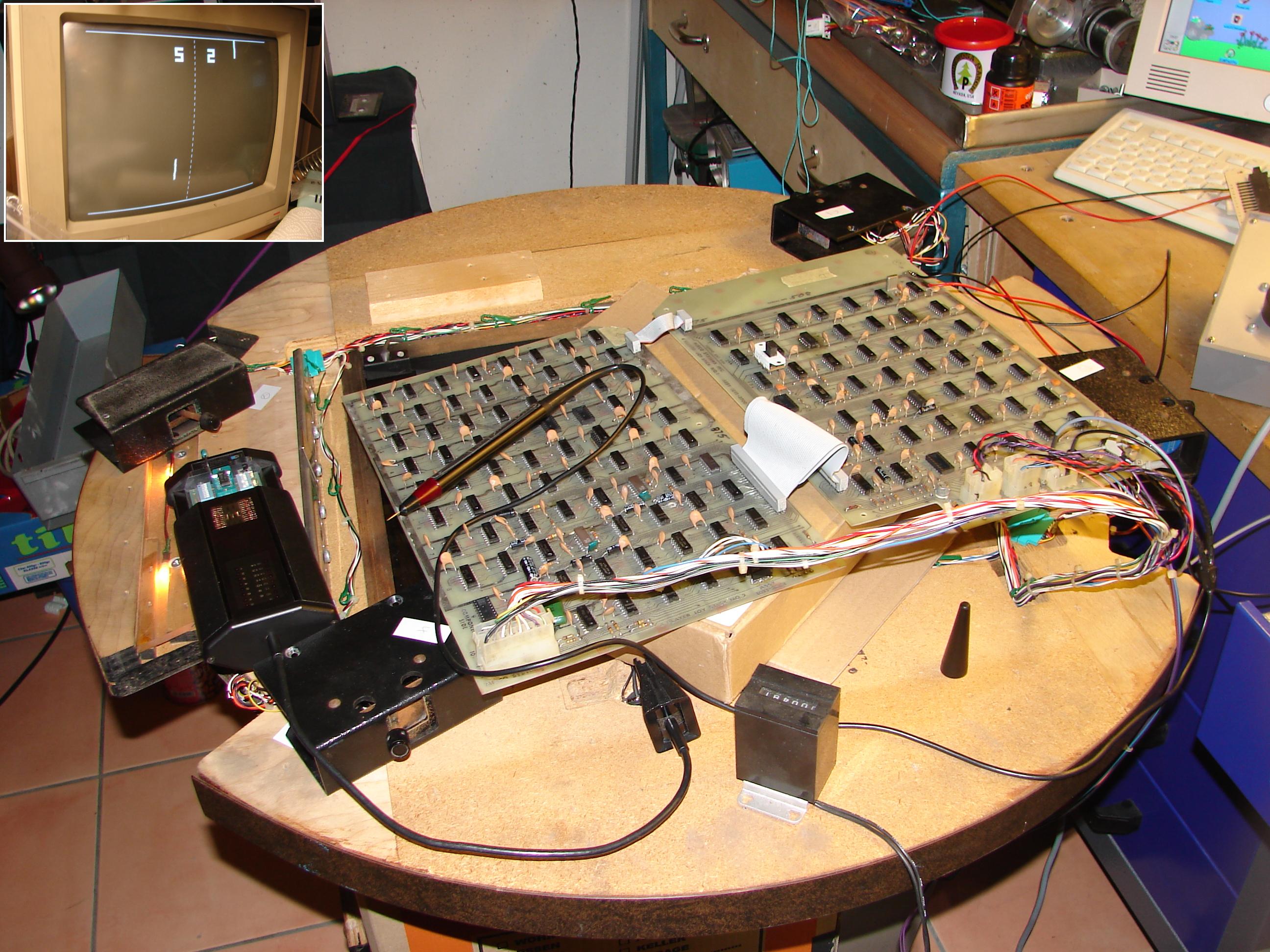
I have received two such machines as a gift and will try
to get one working. The Monitor is a 19" b/w from MOTOROLA M5010-155
which supplies the +5V for the PCB's and also features an Audio
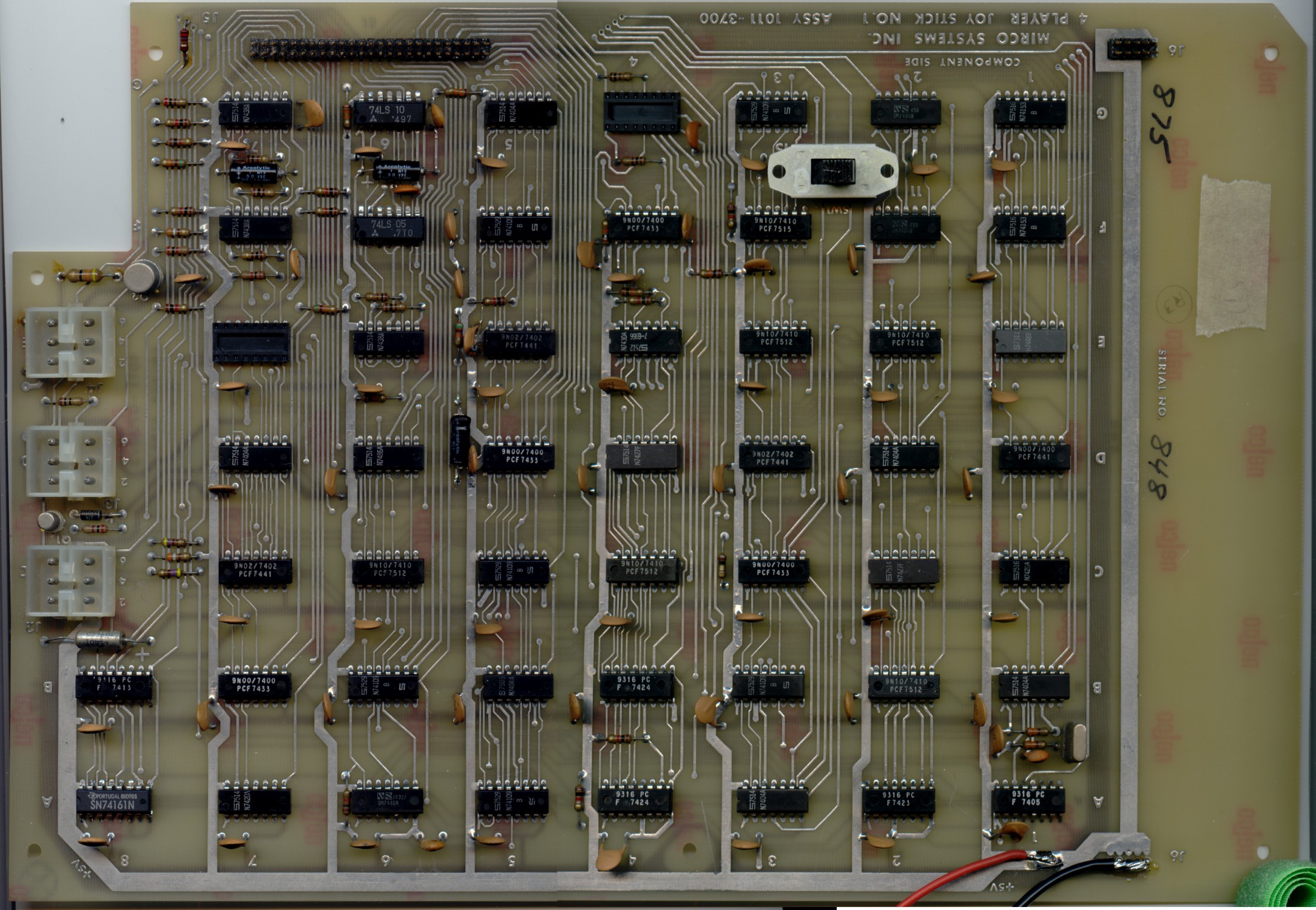
Amplifier. The game logic is spread across two PCB's (1011-3700 and
1011-3701) and ihas ~120 TTL IC's plus some resistors/capacitors and
transistors, there is no CPU however. PCB's are connected via two flat
cables, a larger one for logic information and a smaller one for
+5V/GND supply. Inputs to the PCBs are +5V/GND, analog controls,
coinswitch, mode switch, start switch. Outputs are Video Signal, free
game LED, coin door illumination and unamplified sound.
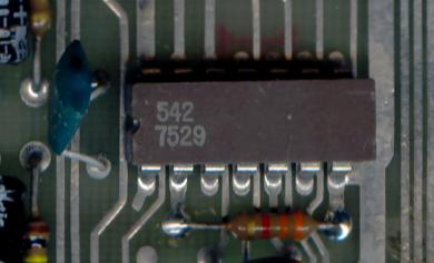
Question:
What is this for a kind of chip?
Its output is a square wave, with duty cycle changing per the
analog controls/potentiometer.
Please click here if you
know!!!
19.
February 2011 -
Repairing PCB's
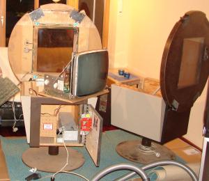
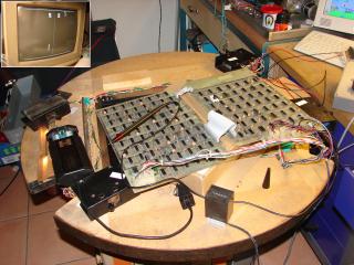 When
switching on the two games, neither did work - no sound, no video.
Decided to check the PCB's first rather than the monitors and so put
them on my bench, with the empty cabinet and its
controls/wiring harness nearby (right picture), so I could easily plug
it into the
PCBs. Connected power from a switching PS, just +5V needed - easy. The
first PCB set behaved as expected, nothing worked. For the second one I
was able to find an output signal at one of the connectors, that looked
like a Video signal and indeed, a playfield showed on the monitor - but
no ball. In the meantime both PCB sets doe show a ball and paddles,
after a handfull of defective TTL chips identified and replaced. Still
some more problems to solve as the Balls doesn't rebounce from paddles
or playfield sides and only two paddles showing on one PCB set.
Continuing my work here .... When
switching on the two games, neither did work - no sound, no video.
Decided to check the PCB's first rather than the monitors and so put
them on my bench, with the empty cabinet and its
controls/wiring harness nearby (right picture), so I could easily plug
it into the
PCBs. Connected power from a switching PS, just +5V needed - easy. The
first PCB set behaved as expected, nothing worked. For the second one I
was able to find an output signal at one of the connectors, that looked
like a Video signal and indeed, a playfield showed on the monitor - but
no ball. In the meantime both PCB sets doe show a ball and paddles,
after a handfull of defective TTL chips identified and replaced. Still
some more problems to solve as the Balls doesn't rebounce from paddles
or playfield sides and only two paddles showing on one PCB set.
Continuing my work here ....
26.
February 2011 -
Capturing Schematics
As a side work I have started to capture the schematics, focussing
on the areas where I see wrong levels of signals. See the 'Links'
section below to find the current status of the 3700 and 3701 PCB
schematics.
 6.
March 2011 - It works! We're
95%done, folks 6.
March 2011 - It works! We're
95%done, folks
Today we managed to get one of two PCB sets working. All four
paddles have now collision detection. So now lets take a look at the
monitor. As already noticed, the HV transformer had the clamp for the
ferrite core broken, so the two halves of the ferrite were loose. In
the meantime I had bought 4 brass rods from EBAY, 2.5mm diameter and
300mm long and made a new clamp from that by bending it into a U-shape
and adding two M2.5mm threads at the ends. The monitor also supplies
+5V to the PCB's, which was flat at 4.6V and could not be adjusted.
After some measuring I replaced what was a µA741 Op-Amp
(Motorola
designation was T3F -> weird!). Lastly a pot on the Audio Amp
was
defective, easy one.
Moved the whole stuff upstairs and put all back into the Cab, after
giving it a good cleaning. To be done :
- Paint the large foot (cast iron)
- Add a lock
- Replace the turn knob for game difficulty
selection
- And : Do the second machine :)
For all who are interested, I have uploaded a video, see link section
just hereafter.
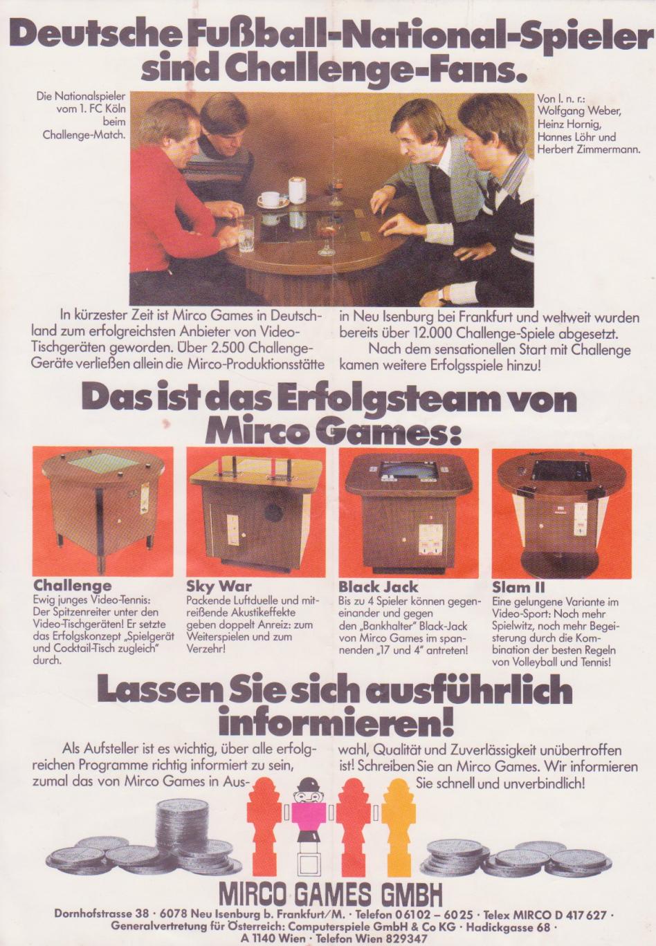
14.
March 2011
- New Info, this is SLAM II
Thnaks
to my friend Laschek, who found a Mirco Games Flyer, this seems to be
SLAM II (not SLAM) with the Mode Select Switch and Start Pushbutton on
top of the game. See his scan here.
» SLAM
(MIRCO GAMES) - Links
SLAM
II Service Manual - includes Motorola M5010-155 and M7010-155
schematics
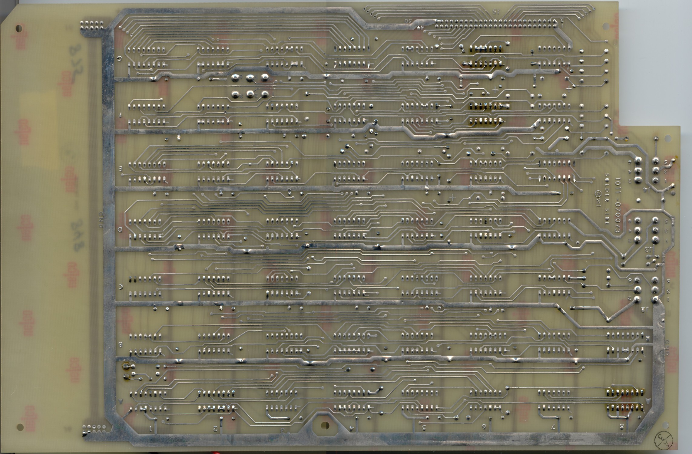
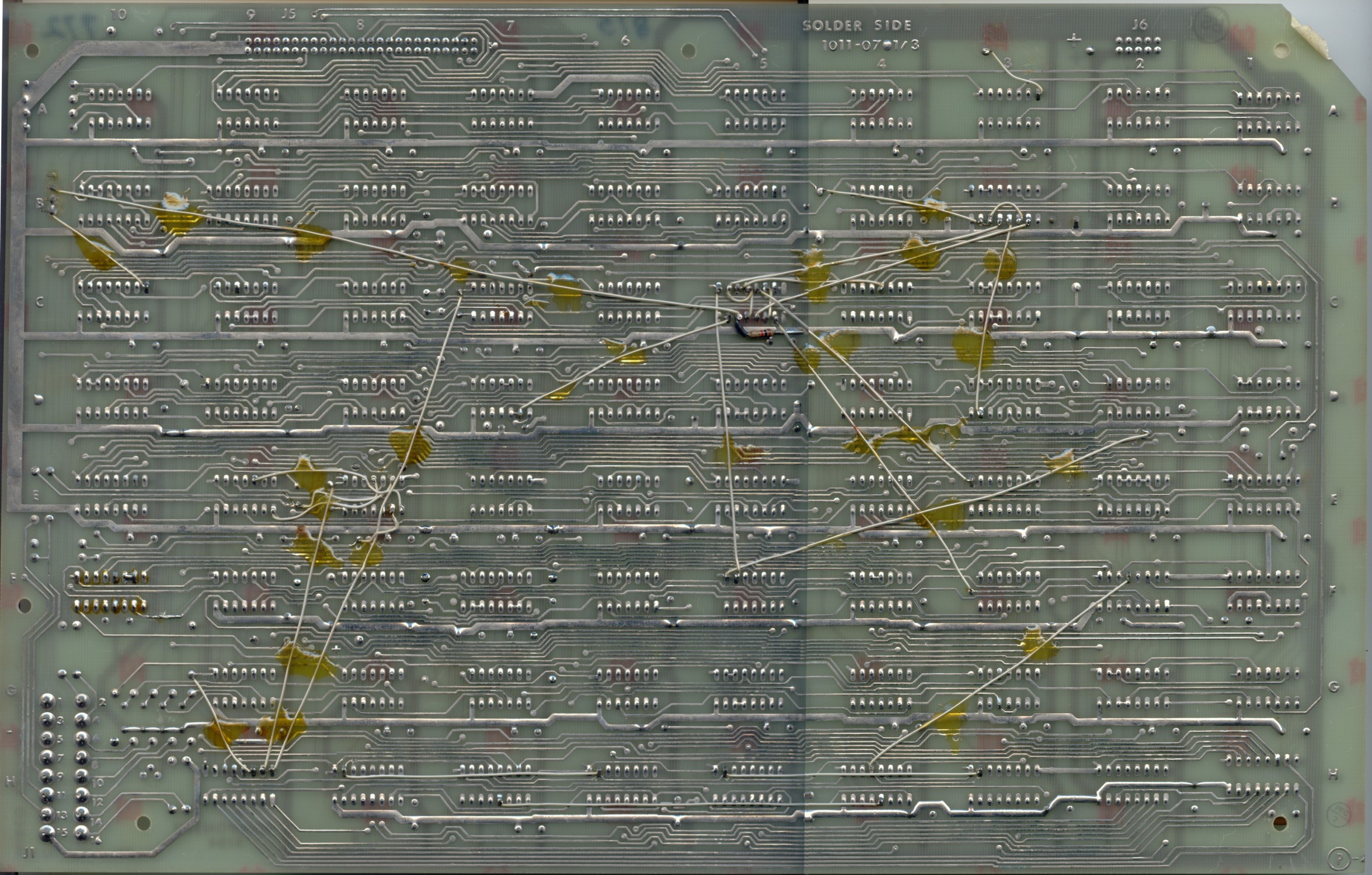
PCB3700-top,
PCB3700-bottom,
PCB3701-top,
PCB3701-bottom
- pictures of the two games PCBs
IC
types used and their placement
Schematics 3700
and 3701
as PDF - Current version of Schematics being captured, this is
work-in-progress
Video
of SLAM II (Mirco Games) game working NEW!!!
Flyer
from Mirco Games - see bottom right for SLAM II picture NEW!!!
|
|
|
|
|
|
|
|


